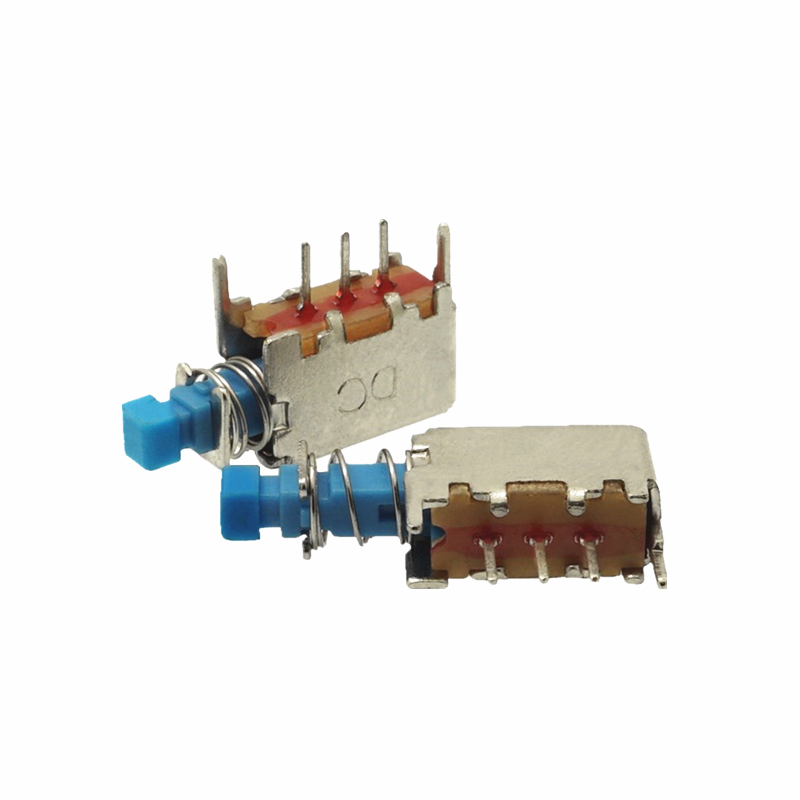
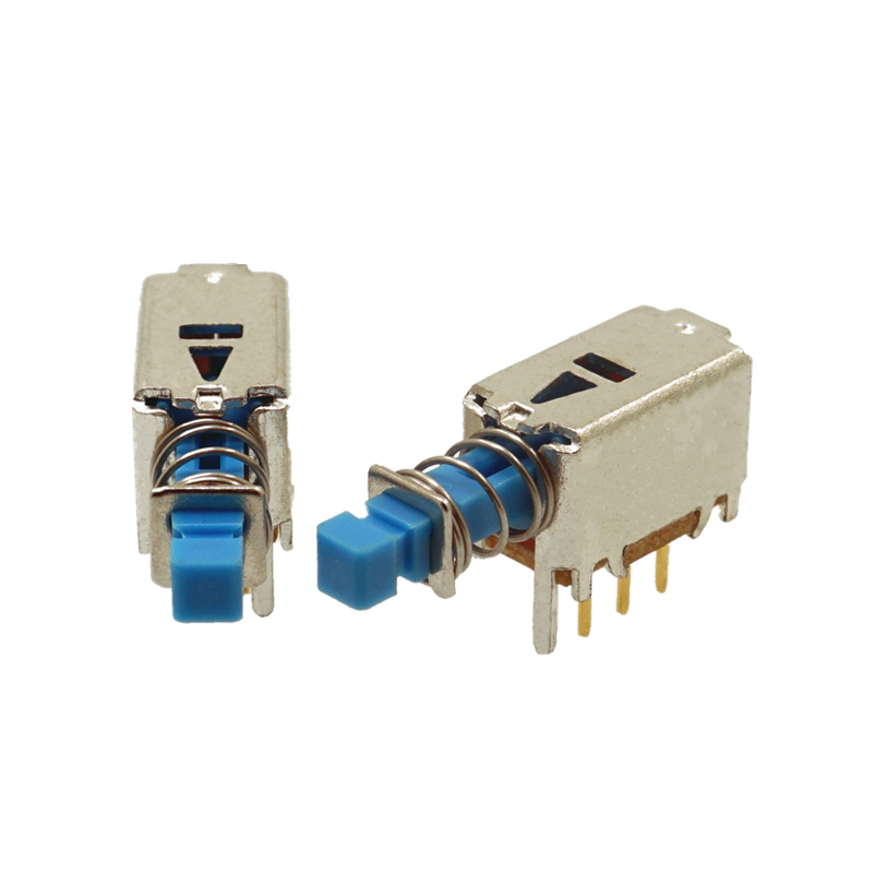
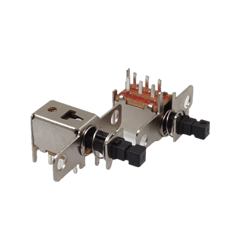
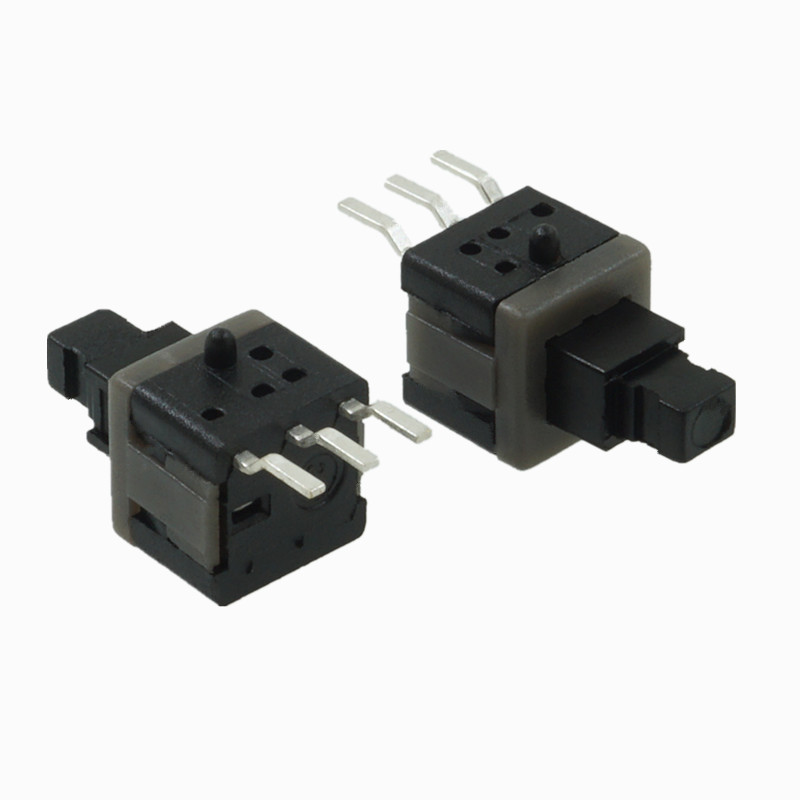
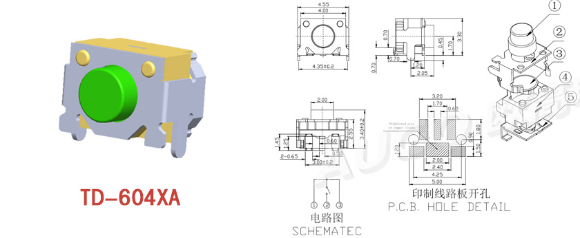
Structure diagram of key switch composition design and principle
The simplest switch has two pieces of metal called contacts. When the two contacts are in contact, the current forms a loop, and when the two contacts are not in contact, the current opens. The degree of corrosion resistance of the contact metal should be considered when using it, because most metals will form insulating oxides when oxidized, which will cause the contact to fail to work properly. Factors such as electrical conductivity, hardness, mechanical strength, cost, and whether it is toxi
- Classification:Key switch news
- Author: AUGO Electronics
- Release date:2022-02-20 18:38:24
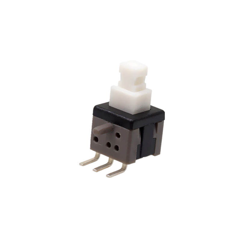
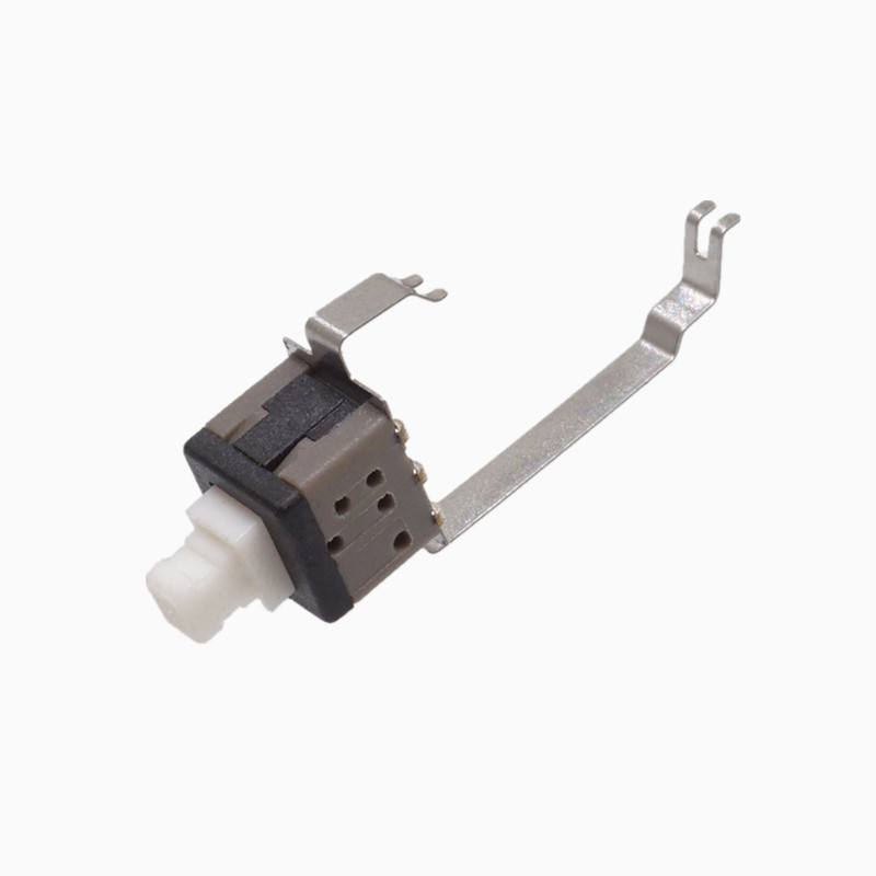
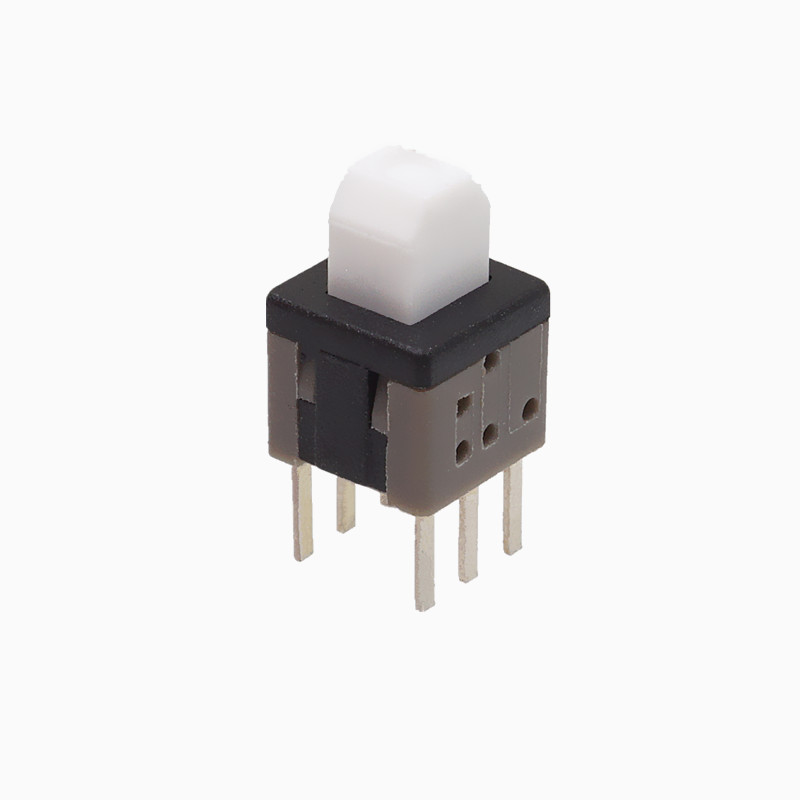
The simplest switch has two pieces of metal called "contacts". When the two contacts are in contact, the current forms a loop, and when the two contacts are not in contact, the current opens. The degree of corrosion resistance of the contact metal should be considered when using it, because most metals will form insulating oxides when oxidized, which will cause the contact to fail to work properly. Factors such as electrical conductivity, hardness, mechanical strength, cost, and whether it is toxic should also be considered when using contact metal. Corrosion-resistant metals are occasionally plated on the contacts, but are generally plated on the contact surfaces of the contacts to avoid oxides that affect their performance. Sometimes non-metallic conductive materials, such as conductive plastics, are also used for the contact surface. In addition to the contacts in the key switch, there will also be movable parts to make the contacts conductive or non-conductive. The switches can be divided into lever switches, Key switches, rocker switches, etc., and the movable parts can also be other types of mechanical connections.
How it works:
Close the power switch K2, and then press the button switch K1. At this time, the crystal diodes V1 and V2 are turned on, and the relay is pulled in. At the same time the power supply charges the capacitor C. When K1 is disconnected, since C has been charged, it will be discharged through R and V1V2, thus maintaining the triode to continue to conduct, and the relay is still closed. After a period of discharge, when the voltage between the two poles of C drops to a certain value, it is not enough to maintain the continuity of the triode, and the relay is released. The time interval from K1 disconnection to relay release is called delay time. It depends on the size of R and C. Generally, when C is 100 microfarads, adjusting the adjustable resistor R can obtain a delay time of 10 seconds to 90 seconds. If C is 1000 microfarads, the delay time can reach more than 5 minutes.
Key Switch has a small contact resistance load, The advantages of precise operating force error and diversified specifications have been widely used in electronic equipment and white goods. Because of the environmental conditions of the key switch (elastic force with pressure less than 2 times/environmental temperature and humidity conditions and electrical performance), large equipment and high-load buttons are directly replaced by conductive rubber or dome switch hardware shrapnel, such as medical equipment, TV. machine remote control, etc.
Key switches are mainly used for color TVs, black and white TVs, audio equipment, VCRs, video cameras, computers, game consoles, fax machines , walkie-talkies, batons, machine tool controls, copiers, printers, electronic instruments, meters and other household appliances.
Back to list